One issue that has caught quite a few people out when they build our Raspberry Pi robot kit, is the issue of power. The kit comes with a 6xAA battery holder, but the trouble is, not all AA batteries are the same, which is easy to overlook when you’re grappling with all the other complexities of building a Raspberry Pi robot. ![]()
We recommend that the robot be powered with good quality, high capacity, rechargeable (NiMh or NiCd) batteries, such as Duracell 2400mAh NiMh . Non-rechargeable (Alkaline) batteries are not recommended as they will struggle to provide enough current to power both the Pi and the motors of the robot.

Good for robots

Bad for robots

Pretty (and also good for robots)
As an alternative to AA batteries, we’re now selling the TeckNet iEP387 USB power bank which can be used to power the entire robot. The power bank is more expensive that the cost of 6 AA rechargeable batteries, but you get the advantage of increased runtime (approx 5 hours compared to 3hrs for the NiMh Duracells), and you don’t have to buy a battery charger.
In this blog post we show you how to use the power bank with the robot.
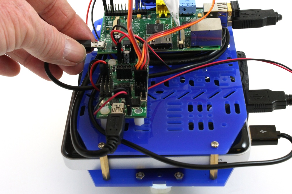
Connecting the Battery to the Robot
Please Note: If you are using a USB battery pack to power the Pi and mini driver, then you do not need to use the UBEC which we’ve started to supply with more recent versions of our Raspberry Pi robot.
Once you’ve built the robot following these instructions, Slide the iEP387 USB power bank into the chassis behind the wheels.
The iEP387 should come with 2 USB cables, a micro USB cable for powering the Pi, and a USB cable with 2.54mm connectors for connecting to the Mini Driver, and powering the motors. First plug the micro USB cable into the 5V 2.1A output of the iEP387 (the Pi needs this) and connect it to the power connector on the Pi (the extra cable can be wound around the Raspberry Pi mounting struts).
Secondly, use the USB power cable with red and black leads, and 2.54mm connectors to attach the 5V 1.0A output of the iEP387 to the battery pins of the Mini Driver (marked + and – next to the mini USB connector). The red wire should attach to the + pin and the black wire should attach to the – pin. Don’t worry if you get them the wrong way round though, as the Mini Driver has reverse bias protection.
Connecting the iEP387 USB Power Bank to the Robot
Make sure that you leave a bit of slack in the cables so that you are able to slide the iEP387 sideways slightly and press the on/off button.

Turning on the iEP387 Power Bank
Turning on the Robot
To turn on the robot, first switch on the power switch on the Mini Driver. This is important in order to provide power to the motors. Then slide the iEP387 sideways, and press the power button. This should turn on the robot.
Turning off the Robot
To turn off the robot you need to unplug the micro USB connector from the Pi, and turn off the power switch on the Mini Driver. This is not as neat as we’d like it, but there’s not really an easy way (without adding more hardware, and therefore more cost) to stop the Pi from drawing power from the power bank.

Unplug the micro USB cable to turn off the Pi
Pulling the power from the Pi shouldn’t damage anything as the robot’s software doesn’t write anything to the SD card. However, it’s always nice to let the Pi shutdown cleanly if possible, and so to do that you can use the shutdown button on the robot’s web interface.
Updated: Extra Photos to Show Installation of Battery
I’ve had a couple of people say that their battery pack touches the wheels so have posted the following pictures to try to clarify things. The pictures are not great quality, but hopefully I’ll have time to update them in the new year.

There should be a small (approx 2mm) gap between the battery pack and the wheels

The battery pack should be held back by the plastic motor tabs.
As an alternative to inserting the battery pack in from the side, it’s also possible to remove the central support and slide the battery pack in from the front. This is a snug fit, but again there should be a few millimetres between the battery pack and the wheels. This gap can be increased by sliding the wheels slightly along the motor axles.

If the central support is removed, the battery pack can be slid in from the front.

There should be a few millimetres of clearance between the battery pack and the wheels.
What is the best way to run the robot via the mains in order to do development work. When I plugged the pi in the mini driver led came on via the usb cable even though it was turned off. I’m not sure if that was ok or not. Also would like to know if the wires from the mini driver to the pi can be left fixed if the pi is powered via the mains. Sorry bit of a newbie.
Hi Dani,
Thanks for the question, and sorry for the delayed reply.
When you plug the Pi into the mains, the mini driver will be powered by the Pi over the USB cable. The wires from the Pi GPIO pins to the mini driver can be left connected, they won’t do any harm and just provide another way for power to get from the Pi to the mini driver.
You should be able to do a fair bit of work with the Pi plugged into the mains. The only thing you won’t be able to do is make the wheel motors turn (or if you do it will be incredibly slowly and weakly). In order to driver the wheel motors a battery pack needs to be plugged into the mini driver, and its power switch needs to be on.
Hope that helps. Please let me know if you need clarification on anything.
Cheers
Alan
I think this could help Your bot with power troubles?
http://www.raspberrypi.org/introducing-raspberry-pi-model-b-plus/
Best regards,
Camillo
Yes, it looks like the B+ will use less power and take some of the strain of the Mini Driver’s linear regulator.
I haven’t had a chance to play with a Model B+ yet but I have some on order, and will hopefully be able to update the build instructions for the robot, for people who but the B+, later this week.
Regards
Alan
Maybe also the 4WD chassis could be used as well?
Hi, as I’ve already got a couple of battery power banks is it possible to buy the USB power cable with the 2.54mm connector?
Hi Mark,
Sorry for the delayed reply.
We’re currently a bit short on the USB connectors we use to make these cables, but should hopefully be getting some more in a couple of weeks time. At that point we plan to start offering the cables for sale separately.
Regards
Alan
Thanks Alan. Will order as soon as they are available.
When USB power bank is going to be available ? Currently it is out of stock
Hi there,
Sorry for the delay. We should hopefully have these back in stock by the weekend.
Regarsd
Alan
Hi Alan
Is USB power bank in stock now ?
Thanks
Hi Aqil,
Yes, back in stock now. You can find it here.
Regards
Alan
Hello, couple of questions:
Why is the Pi connected to 2.1A out and mindriver to the 1A? I thought minidriver (as it is powering motors) would need more current, and Pi (it only handles camera, wifi dongle *and* minidriver somehow, but this is my next question) less?
If the Pi is connected to minidriver via USB, it acts like a source to the minidriver – what if the minidriver motors are stalled/working hard and are drawing large amounts of current? Is it safe? Shouldn’t minidriver V/Bat selector jumper be set accordingly (docs says it allow switch between 5V regulator/battery, but my experiments showed that no matter what settings, motors draw from 5V regulator, unless I don’t understand it, docs are *very* verbose about it)?
And the last – leaving minidriver on and plugging rpi off allows pi to draw current from minidriver (it doesn’t shut if USB is still connected). Is it safe? Or the current is not that big and it should be avoided (it can be quite convenient to use this fact to switch pi to the mains).
Hi there,
Thanks for the questions. I have been telling people to connect 2.1A to the Pi and 1A to the Mini Driver, because there seemed to be situations with the old Model B Pi, and with some WiFi dongles other than the Edimax EW-7811Un that we recommend, where the 1A just didn’t seem to be enough. I can’t belive that the current draw was going over 1A, but it may have been getting very close, or perhaps there were times (i.e. during bootup) where the 1A port couldn’t keep up with a quick rise in the amount of current demanded. I didn’t have time to investigate this in much detail, but the Mini Driver and motors always seemed to be happy with just 1A so I recommended 2.1A for the Pi to try to give people maximum stability. With the new Model B+ and its lower current draw, I would imagine that it would probably be much more stable running from the 1A port and there have been some posts on our forum, with people suggesting that 1A for Pi and 2.1A for motors works best for them.
I haven’t had any problems with the motors stalling, and the mini driver drawing current from the Pi. I would hope that even if the Pi had a powerful supply attached to its microUSB input, then the polyfuse on its input should blow before any damage is done to the Pi.
As it is, the motors should only be drawing current from the batteries. I know that it is possible to drive the motors very slowly from just USB power, but am not quite sure what mechanism is causing this to happen as Dagu don’t supply a schematic for the mini driver and so I need to investigate further at some point. As I understand it, the atmega8 of the mini driver is powered by the 5V regulator (which hangs off VBAT) and sends PWM signals to the mini driver’s h-bridge which then supplies VBAT to the motors. I can only imagine that if the power switch is off then somehow the USB 5V is going back through the linear regulator, onto VBAT and then into the motors. Either way, I don’t think that enough current could be drawn this way to cause a problem.
With regards to the 5V/VBAT selector jumper, this only sets the voltage that goes to the middle set of pins on the digital (D2 to D13) connectors. This is meant to be used so that you can choose what voltage to supply servo motors connected to the mini driver. The small plastic servos we supply for the robot’s pan/tilt neck run well at 5V, and may be damaged if run at high battery voltages so I would recommend that that jumper is left in the default 5V position, unless you have a good reason to move it.
Finally, supplying the Pi with current from the Mini Driver should by and large be safe. For the new model B+, it seems as if USB back powering is now not possible (or at least not a problem). For the old Pi, I imagine that it would only be a problem if you had something on the GPIO pins trying to draw a large amount of current, and very big batteries attached to the mini driver. Even then, the 1A linear regulator would likely give out before too much current got to the Pi.
Anyway, hope those answers helped (and gave some clarity in some areas). Please let me know if you want more detail on any specific areas.
Regards
Alan
Hi,
As an avid rc fan i have lots of electronics lying around.
Is it possible to use two ubecs connected to one (lipo) battery and power the robot and Pi separately?
Or could I even use one ubec (i have some 7a 5v versions) to power both?
thanks!
Hi Hans,
I’m trying to learn more about the RC hobby world, as they seem to have a number of cool solutions for quite a few different problems in the hobby robotics world.
We have now started to include a UBEC in our Raspberry Pi robot kit because it gives great battery life when running off NiMH (see this blog post). I haven’t done it myself, but using LiPos should work just as well if not better.
Regards
Alan
Thanks for the reply!
I’ve seen your blog, but that uses a ubec between the robotboard and the PI.
My setup would be to power the board and the PI directly with each their own 5v ubec.
The ubecs would both draw power from the same 7.4 lipo
so one lipo feeding two ubecs
one ubec powering the board
one powering the pi
To my knowledge that would provide a more stable feed.
But I dont know if this will short the two ubecs
Hi Hans,
We connect the UBEC to the Mini Driver, but the pins it’s connected to are effectively the terminals of the battery i.e. the full battery voltage is going into the UBEC, and then being regulated down to 5V before going to the Pi.
So, the way our robot works is, we have one battery pack with 2 voltage regulators attached to it. The first voltage regulator is the 5V linear regulator on the mini driver board, and this powers the Atmega8 microcontroller and any sensors or servos attached to the mini driver. The second voltage regulator is the much more efficient UBEC and this produces 5V for the Pi. The wheel motors of the robot are powered by unregulated battery voltage.
Now you could replace the battery pack in this setup with a Lipo pack, the main limit is that according to the manual the max voltage that can be supplied to the mini driver is 9V.
With your suggested setup you would be powering the Pi in the same way as us (i.e. battery -> UBEC -> Pi although by the sounds of it your UBEC will be better) but then you’ll be powering the Mini Driver as battery -> UBEC -> 5V Regulator -> Atmega8 and the motors as battery -> UBEC -> motors. This is fine, you won;t get any shorts, and it’s effectively what happens when we run the robot from a USB powerbank, but you’ll only be supplying 5V to the motors so it’ll go a bit slower than if the motors were connected directly to the battery.
Hope that makes sense? Let me know if there were any areas that were unclear and I can exercise my rubbish artistic skills and try to draw some diagrams.
Regards
Alan
Has anyone noticed a tight fit with the power bank to the point of it touching the wheels? I can shim the powerbank a bit and keep it from rubbing, which i think might be easier than trying to adjust the motors and mounts to get me an extra bit of clearance.
I realize now after looking at the motors that there is no way to slide them back, as the mounting screws go thru the motor body (forgot about that), so they are locked in place. Will need to look at a solution that holds the battery pack out of the way.
Hi Don,
I’m finding this very confusing, as I’ve never had any problems with the powerbank touching the wheels. The fit is a bit tight, but I’ve always found that there’s a small (approx 2mm) gap that allows the wheels to turn freely.
Having said that, I have had another customer report the same problem recently so I’m keen to try to work out wht’s going on here.
I’ve updated the post to include the pictures that I sent to my other customer, trying to clarify the issue (haven’t heard from him yet whether this improved things). Apologies that the images aren’t great quality, it’s tough to get in close to photograph the important areas, I’ll try to take better ones in the new year.
If you can see anything different between your kit, and the photos I’ve uploaded, I’d be very interested to hear. Are the tyres on your wheels thicker for instance?
Regards
Alan
Not seeing where you posted additional pics..?
My guess its a combination of tolerances, being that its a tight fit typically. Variations in the battery pack, thickness of the wheels, etc., all coming together.
Sorry, must have mucked up with WordPress somewhere. Hopefully you should be seeing the images now?
Manufacturing tolerances could be causing the issue but we’ve been selling the battery pack since June and not seen any problem until now, when there seem to be at least 2. Any extra information or pictures you can provide would be much appreciated.
Regards
Alan
If I slide the battery pack in and position it just right, it sits there with some clearance. Not much, but the tires and case do not touch.
Any movement, and the clearance disappears. The battery pack just does not stay in a position where it can avoid touching the tires.
Looking at it some more, and comparing with the pics, I’m thinking its the thickness of the tires. And it makes sense, considering the likelihood that those are manufactured under much looser tolerances than the battery pack case. I’ve ensured the motor mounts are tight and everything is positioned correctly.
I can try to get some pics, but clear closeups that show the gap (or lack thereof) will be tough. Going to stew on this a bit and see if I can come up with a fix that will take care of the issue.
Hi Don,
Thanks for persevering with this. When I get back into the office on the 5th I’ll try building another robot from scratch to see if I can recreate the problem. It is possible that Dagu (the company which make the 2WD chassis) may have done something like change the wheels to use different tyres without us noticing.
I’d be interested to know if the alternative method for positioning the battery pack works for you? This seems to work well for another customer, possibly using someting like velcro to hold it in place. If it works for you then I might change the instructions to recommend it, and include some velcro with the battery packs.
Regards
Alan
I haven’t tried the alternative method, but will take a look at it. Probably need to craft another cable if I do so.
I bought my battery pack from Amazon, so had to make my own cable for the controller, but comparing to what you offer, its the same unit, so I would assume that eliminates the possibility of variations in the size of the battery pack.
I placed an order for some Dasu parts last week from a US based seller, didn’t know about this issue at the time, otherwise I could have ordered a second set of wheels to compare.
I have built the robot and got it working. When I tried to turn it on to day, the it does not appear as a wifi network. It also turns itself off after about half a minute
Hi there,
What USB WiFi dongle are you using? Also, what are you using to power the robot? If you’re using non rechargeable (alkaline) batteries, could you use rechargeable (NiMh) batteries instead?
Regards
Alan